CNC 5 Axis Milling of Airfoil Parts: What You Need to Know
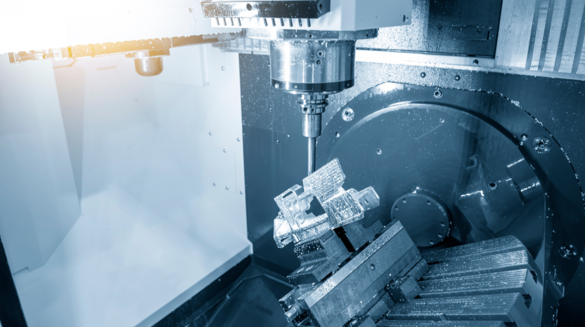
Airfoil parts are critical components of the aircraft needed to control airflow, improve lift, and aircraft performance. They are intricate and highly complex components and thus manufactured using 5-axis CNC machining.
In this blog post, we explore all you need to know about CNC 5-axis milling of airfoil parts.
What are Airfoil Parts?
Airfoil parts are curved wing-shaped components designed to control airflow in an aircraft.
They help to improve aircraft performance by enhancing lift and eliminating drag during flight. They comprise highly intricate geometries and are therefore designed using a 5-axis CNC machining process.
Because of their valuable function in aircraft, they are designed to withstand several flying conditions and pressure and to help enhance flight stability and fuel efficiency.
Examples of Airfoil Parts
Aerospace Turbine Blades
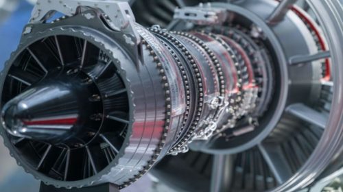
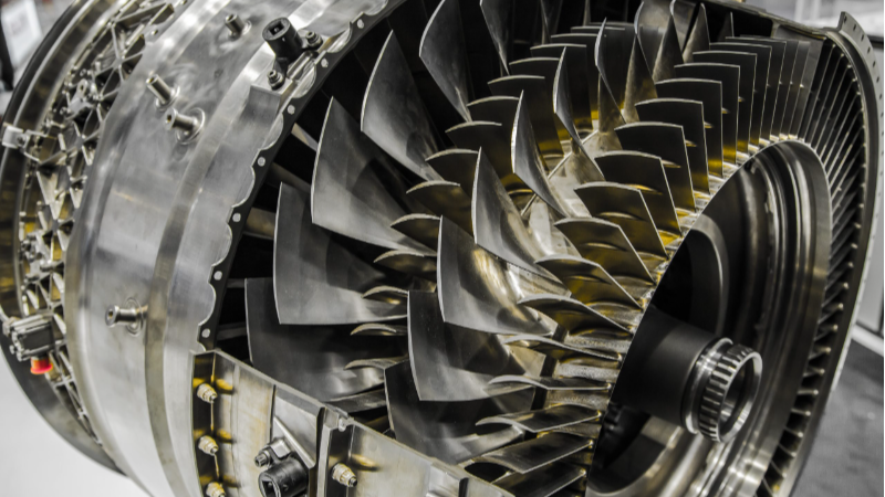
Aerospace turbine blades are essential parts of an aircraft turbine engine that derive energy from extremely high-temperature and high-pressure gases generated during combustion, causing the turbine to spin or rotate and powering the aircraft.
Turbine blade airfoils are curved in shape and withstand several harsh conditions, and as such, they are made from durable, high-performance alloys.
Aerospace Vanes and Nozzles
Aerospace vanes and nozzles are components within the aircraft turbine engines that direct and control airflow.
Vanes are usually static, and they control hot gases from the combustion section to the turbine blades. Nozzles, on the other hand, help create thrust by increasing the rate of gas flow.
Both components are complex-shaped, designed to withstand extreme conditions, made from high-grade alloys, and essential in enhancing turbine engine performance and reliability.
5-axis CNC Milling of Airfoil Parts
Here are the key points to note in CNC 5-axis milling of airfoil parts:
Overview of the Processing Method
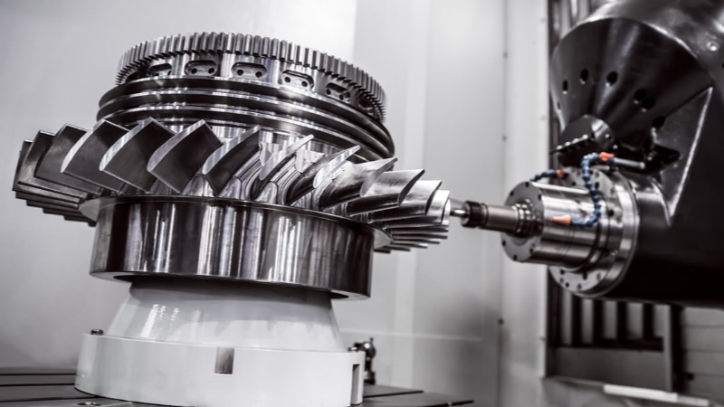
Airfoil parts are usually machined using 5-axis CNC milling due to their intricate and complex geometry.
For the machining to take place, the airfoil material is usually held firmly on the A-axis to enable a 360-degree rotation while the cutting tools move along the C-axis, with the pneumatic tip also firmly tightening the part in place.
Machining of the airfoil part takes three steps, which include roughing, semi-finishing, and finishing. The most effective method to machine airfoil parts is through 5-axis simultaneous machining, which allows high-speed spiral milling and produces the best-shaped airfoil part.
With the use of a face milling cutter, material is being cut efficiently; however, it cannot maintain a static swing angle for the C axis.
To prevent distortion around the root, the area closer to the root is milled with a ball-end milling cutter, ensuring it is not too deflected from the C-axis. This helps ensure the airfoil shape comes out as expected.
Data Preparation
Before the actual airfoil machining begins, the design data must be clearly prepared. Airfoils used in turbine engines are usually in 3D shape, comprising many sections making up the component.
To begin the data preparation, the design coordinates must align with those of the machine. This will help ensure that the parameters and references of both the design and the machine that will mill the airfoil are coherent.
The machining of an airfoil is usually done with a high-speed spiral cutting technique, so the shape comes out smooth. However, the material used must be free from vertices or sharp sections to prevent unusual vibrations or tool damage.
While the design might appear even smooth with 2D sections, vertices, or waves might be experienced along the axis when creating the full 3D shape. This can be adjusted by checking the reference for the sections.
Mathematical Modelling
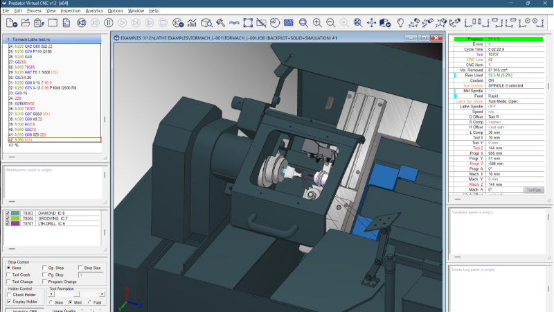
When building an airfoil component, the digital mathematical model of the part is first created so the CNC machine understands exactly what to do when machining.
To begin the modelling procedure, each section of the airfoil is represented as a 2D closed curve and then adjusted or positioned properly to get the 3D model.
Tool Overcutting Calculation
Overcutting occurs when the milling cutter tool removes excess material beyond what’s intended. To prevent this, the cutting angle or the tool diameter will be replaced.
Creating a Coordinate System
To mill the airfoil blade with the CNC machine, a 3D coordinate system will be used. Also, the design reference and machining basis must be coherent to allow for simple programming and the tool setup process.
Determination of Cutting Parameters
When using a 5-axis CNC machine for milling turbine blade airfoils, some key parameters must be mapped out.
These important parameters determine how accurately the CNC machine works, the outcome of the components’ surface and shape. Here are some of them
Parameters of the Fit Curve
For the machine to mill out the blade shape, it moves along three straight linear axes ( X, Y, Z) and two rotational axes (A and C) simultaneously. These two motions are important for efficient milling and getting an accurate contour.
Line Spacing
This refers to the measured length between two tool paths found on the blade. Line spacing affects the surface quality obtained, and thus, the correct parameter for it must be determined.
When the line spacing is too large, that means the milling was quick. However, there will be more rough surfaces and grooves. When there is too little, the surface quality derived will be fine, accurate, and precise. However, the machining procedure will take more time with less efficiency.
Cutting Angle
When machining the airfoil with a face milling cutting tool, choosing the accurate angle between the down surface of the tool and the tangent line of the turbine blade airfoil at the milling section is essential.
Selecting an incorrect angle can result in overcutting. To also determine accurate spindle speed, feed rate, and cut depth, the material used, machining technique, and tool diameter need to be considered.
Tool Path Simulation
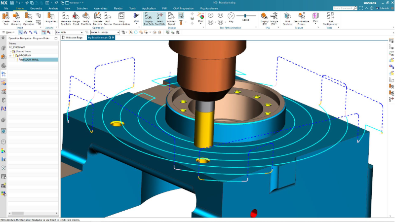
Simulation with the use of computers creates a way for cross-checking what the milling procedure is like before the actual machining is done. With it, you can determine if excess material is cut or if there is too much residual left.
Also, with the simulation process, you can determine the working condition of the machine tool holder. This would help indicate any interference and, as such, prevent accidents or damage in the actual machining process.
CNC Machining the Blade Root
The root machining is also an important part of the turbo blade airfoil manufacturing process. Earlier on, the root is usually made using a blade milling machine with the aid of special forming tools.
Today, the whole machining process of the airfoil part, including the blade root, can be completed in one set using a 5-axis CNC machine, from roughing, semi-finishing, and finishing. Machining of the blade root thus follows the same step as that of the blade itself.
Roughing
With roughing, the material is cut out quickly using a huge diameter cutter that removes only about 0.2 mm of excess material on the root tooth.
Semi Finishing
With this step, more excess materials are cleared, giving an even and accurate finishing allowance
Finishing
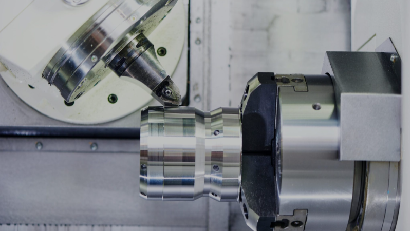
Finishing is the last and most vital stage. To reduce surface roughness, finishing is sometimes carried out as a one-way process. Although this increases machining time, it helps achieve better surface quality.
AeroCNCParts: Your Trusted Turbine Airfoils Manufacturer
AeroCNCParts is a leading and expert manufacturer of cutting-edge aerospace components. From turbine airfoils to several other intricate aircraft parts, we ensure the accurate precision, reliability, and efficiency of our parts.
Our manufacturing process aligns with stringent NADCAP, ISO 9001, and AS9100 regulatory standards, ensuring that quality components are delivered right on time. When you work with us, we guarantee you 100% inspection, full material traceability, FAI and PPAP support, and much more. Contact us now.
Conclusion
CNC 5-axis milling of an airfoil part is an advanced machining process that helps ensure the reliability and efficiency of the airfoil component. Because the machining process can handle parts with complex geometries and designs with ease, it remains the most valuable method for optimal airfoil performance, quality, and surface finishing.

Kim
Kim oversees engineering operations, including complex process planning, DFM reviews, and solving challenges associated with high-precision aerospace parts. He specializes in strict tolerance control and machining complex geometries essential for avionics, turbine components, and structural frames. Outside of work, he enjoys the precision and strategy of playing snooker.