Aerospace CNC Machining: A Practical Guide for Engineers and Buyers
Last updated: October 7, 2026
Aerospace CNC machining is the computer-controlled cutting of flight and ground-support parts from bar, plate or forgings, to a customer drawing, with tight tolerances and full traceability. The cutting itself is the same technology used in any precision shop. What makes the work aerospace is the system around it: material bought to AMS or ASTM specifications, a first article inspection, finishes processed to military and AMS specifications, and records that link every part to its material heat and inspection results. If you are sourcing parts rather than reading up, go straight to our aerospace CNC machining services.
What is aerospace CNC machining?
A programmed machine removes material until only the geometry of the drawing remains. Compared with general industrial machining, five things change:
- Material specifications. Stock is ordered to a named specification (AMS, ASTM or the customer’s own) and arrives with a mill certificate. The heat or lot number follows the part.
- Documentation. A first article inspection proves the process, then batches ship with the Certificate of Conformance, dimensional records and material certificates, as requested by the customer.
- Special processes. Anodizing, chem film, passivation, plating and shot peening are run to the specification on the drawing.
- A documented quality management system. Procedures for nonconformances, calibration, training and supplier control are written down and audited.
- Low volume, high mix, repeat batches. Lot sizes are small, part numbers are many, and the same part comes back for years. Repeatability matters more than cycle time.
The customer, as design authority, owns the design, its qualification and its airworthiness. The machining supplier makes the part to the drawing and proves it.
What CNC machining is used for in aerospace
| Part family | Examples | Typical material |
|---|---|---|
| Structural | Brackets, fittings, mounting components, frames, ribs | 7075 and 7050 aluminum, Ti-6Al-4V, 17-4PH |
| Avionics and electronics | Housings, EMI shielding frames, connector plates, sensor mounts | 6061 and 7075 aluminum |
| Thermal management | Heat sinks, cold plates | 6061 aluminum, copper |
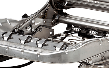
| Interior | Seat frames, hinges, bezels, partition fittings | 7075 aluminum, titanium, PEEK, Ultem |
| UAV, eVTOL and space | Brackets, fittings, antenna parts | Aluminum, titanium, stainless steel |
The structural row covers the structural support components that carry and locate equipment; the avionics row covers avionics enclosures, usually thin-wall housings with tight flatness on mating faces; the interior row covers cabin interior parts, where cosmetic surfaces and plastics qualified by the customer come in. For space programs, see satellite components and their machined parts. Engine parts are a separate specialty and are outside the scope of this guide.
Have a drawing? Get it quoted with the material spec, finish and documentation you need.
CNC processes used for aerospace parts
3-axis milling
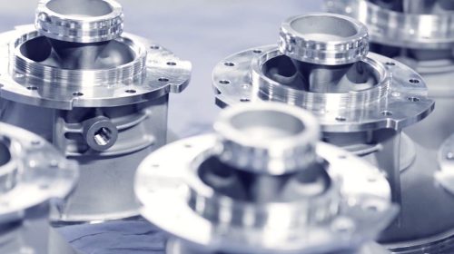
The workhorse for prismatic parts: plates, connector plates, simple brackets and pockets. Parts with features on several faces need several setups, and each setup adds a datum transfer: the part is re-clamped and re-located, and errors between faces add up. Dedicated fixtures keep repeat batches on the same locating points.
5-axis milling: 3+2 and simultaneous
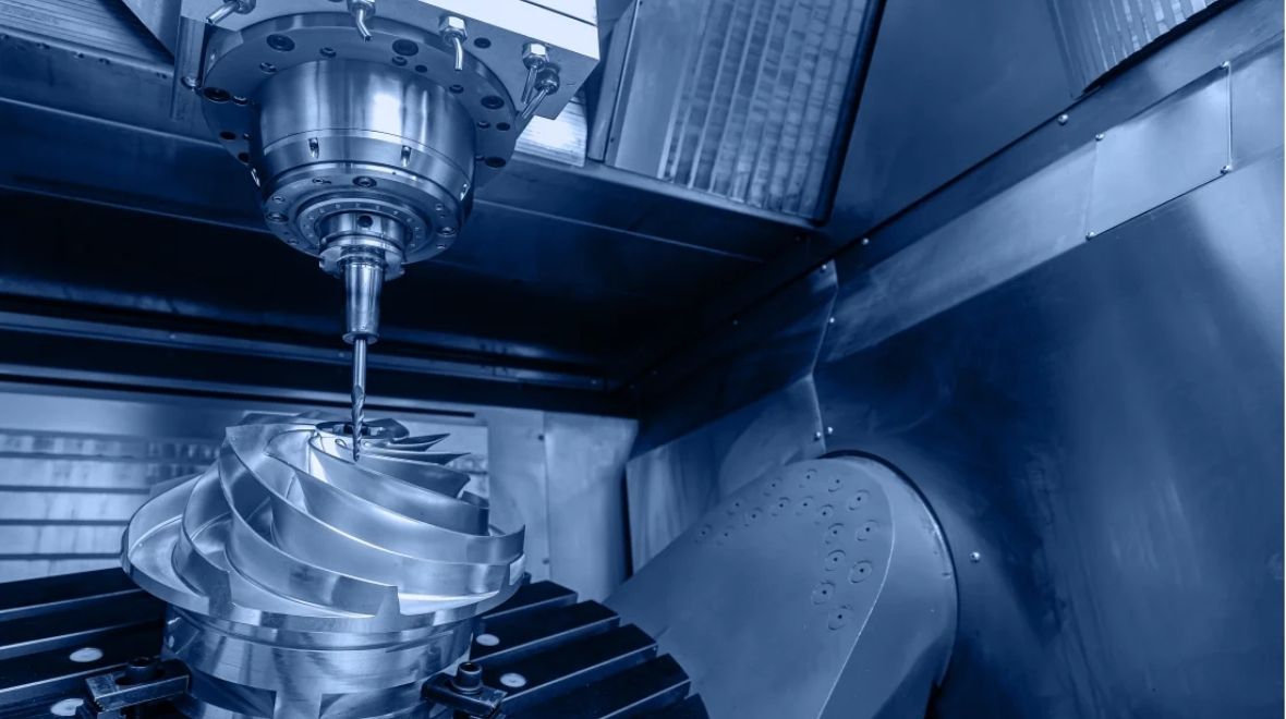
In 3+2 machining, the two rotary axes tilt the part to a fixed angle and lock, then the machine cuts as a 3-axis mill. Simultaneous 5-axis moves all axes together to follow contoured surfaces. Both reach several faces in one setup, so features share one datum scheme; see 5-axis aerospace machining.
Turning and mill-turn
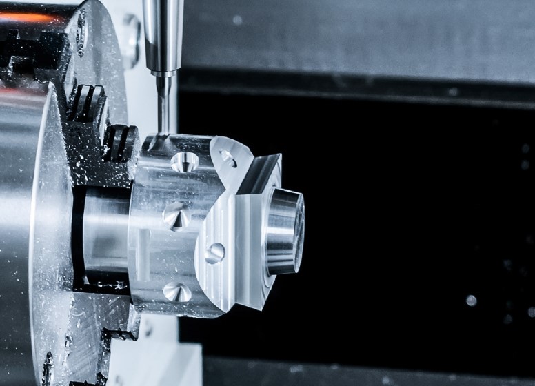
Turning produces shafts, bushings, pins and round housings with concentric diameters. Mill-turn machines add milled flats, cross holes and slots in the same setup, which keeps those features true to the turned axis.
Swiss turning
A sliding-headstock lathe supports the bar close to the tool, which suits long, slender parts such as small pins and spacers.
EDM
Wire EDM cuts profiles and sharp internal corners; sinker EDM burns cavities a cutter cannot reach. Both work regardless of material hardness. EDM leaves a thin recast layer on the cut surface, and some aerospace drawings limit or forbid it on stressed features, so the drawing note decides whether a feature can be EDM-cut or needs a finishing pass.
Grinding
Cylindrical and surface grinding produce diameters, flat datum faces and finishes beyond what turning or milling can hold.
Aerospace materials and how they machine
| Alloy | Spec example | Why it is used | Machining notes |
|---|---|---|---|
| Aluminum 7075-T6 / T7351 | AMS or ASTM plate and bar specs | High strength-to-weight structure | Machines well; T7351 is stress-relieved and resists corrosion cracking better |
| Aluminum 7050-T7451 | AMS plate specs | Thick structural sections | Stress-relieved plate, stable after heavy stock removal |
| Aluminum 6061-T6 | AMS or ASTM specs | Housings, general parts, weldable | Easy to machine; anodizes very well |
| Aluminum 2024-T3 | AMS or ASTM specs | Fatigue-critical sheet and plate parts | Gummy; anodizes less evenly |
| Titanium Ti-6Al-4V | AMS 4911 (plate), AMS 4928 (bar) | Strength at low weight, high temperature, corrosion | Low speeds, rigid setups, high-pressure coolant |
| Stainless 17-4PH, 15-5PH | AMS 5643 (17-4PH bar) | High-strength, corrosion-resistant mechanical parts | Condition (H900, H1025…) changes machinability |
| Inconel 718, 625 | AMS 5662 / AMS 5663 (718) | Strength near heat | Difficult to machine: heavy tool wear, work hardening |
| PEEK, Ultem (PEI) | Customer material spec | Insulating, low-weight functional parts | Heat and stress control to hold tolerance |
Machining time follows the alloy: titanium and Inconel take several times longer than aluminum for the same geometry. More on the alloys we machine in aluminum aerospace parts and titanium aerospace components.
Tolerances, surface finish and inspection
There is no single aerospace tolerance. Each feature carries its own, and general tolerances in the title block cover the rest. Drawings commonly hold ±0.1 mm (±0.004 in) on non-critical features, ±0.025 mm (±0.001 in) on locating features, and tighter values on bearing seats, bores and datum faces. Our tolerance range per feature:.
- GD&T. Aerospace drawings are read to ASME Y14.5: position, profile, flatness and perpendicularity tied to datums. The datum scheme decides how the part is fixtured and measured.
- Surface finish. Drawings often call Ra 3.2 µm on general surfaces and Ra 1.6 or 0.8 µm on mating and sealing faces; finer values usually need grinding.
- Inspection. CMM for 3D features and GD&T, vision (2.5D) measurement for small and flat features, gauges for threads and bores, eddy current for coating thickness.
- First article. The first part of a new number or revision is measured against every drawing requirement and recorded in the AS9102 format.
- Inspection plan. Before production, the plan fixes which features are measured on every part, which are sampled, with which instrument and at which operation. Repeat batches follow the same plan, so results stay comparable from lot to lot.
Finishing and special processes
| Finish | Specification | Typical use |
|---|---|---|
| Chem film | MIL-DTL-5541 | Conductive, corrosion-protected aluminum faces; paint base |
| Type II anodizing | MIL-A-8625 | Corrosion protection and color on aluminum |
| Type III hard anodizing | MIL-A-8625 | Wear-resistant aluminum surfaces |
| Passivation | AMS 2700 | Stainless steel parts |
| Electroless nickel | AMS 2404 | Uniform wear and corrosion layer |
| Shot peening | AMS 2430 | Fatigue-sensitive metal parts |
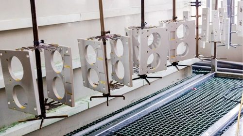
Special processes are performed per the specification on the drawing, and their records join the part’s documentation. Finishes change dimensions, so the drawing should say whether dimensions apply before or after finish. Specs and design notes are on aerospace hard anodizing, and the choice between types in anodizing types and alternatives.
Quality system and documentation
A buyer’s supplier-quality team will ask for the following; we supply these documents on request:
- A documented quality management system; at AeroCNCParts, an ISO 9001-certified quality system.
- AS9102-style FAI report for new parts and revisions.
- CMM and dimensional reports for each batch.
- Material certificates and heat or lot traceability from raw stock to shipped part.
- A Certificate of Conformance (CoC) with each shipment.
- NCR, CAPA and 8D handling of nonconformances.
- Calibration and inspection records for the instruments used on the part.
- Counterfeit-part prevention: material bought from known mills and distributors, with certificates checked at receiving.
- FOD control: clean work areas, chip removal from internal passages, and packaging that keeps debris out.
How we run these checks: quality assurance and inspection.
From first article to repeat production
- First article. Programs, fixtures and the inspection plan are proven on the first parts, and the FAI report closes the loop with the customer.
- Low-volume production. The approved process runs unchanged, with in-process checks on critical features.
- Repeat batches. The same program, fixtures and inspection plan return for each release. A new FAI is needed when the drawing, process or source changes, or after a long gap in production.
Cost per part falls after the first article because programming, fixtures and FAI are one-time work spread over later batches. Batch size, material and inspection level still move the price, and grouping releases into fewer, larger batches lowers setup cost per part but ties up stock; see how machining quotes are calculated. Early-stage prototypes and design iteration are covered by our sister site, AeroRapidProto.
Main challenges
- Thin walls and distortion. Housings and ribs move as material is removed. Balanced stock removal, roughing then finishing, and support during finishing keep walls in tolerance.
- Residual stress in plate. Stress-relieved tempers (T7351, T7451) reduce movement, but large pockets in thick plate can still bow a part. Leaving stock, then re-clamping before finishing, is common.
- Tool wear in titanium and Inconel. Heat stays in the tool instead of leaving with the chip, so tools wear fast and parts work-harden. Tool life is planned, not discovered.
- Burr control. Burrs at intersecting holes and inside passages must be removed and inspected; a loose burr is foreign object debris.
- Finish allowances. Anodize and plating grow the part, so bores and threads machined to final size can end up out of tolerance after finishing. The allowance is machined in, from the growth expected for the specified finish and thickness.
- Measuring flexible parts. A thin housing measured free can read differently from the same housing bolted in its assembly condition. The drawing or the inspection plan should state the restraint condition for flatness and profile checks.
- Long cycle times. Parts machined from solid often remove most of the starting material.
- Material lead times. Aerospace-grade plate, bar and forgings can take longer to source than the machining itself.
Checklist: what to send with an aerospace machining RFQ
- 3D model and 2D drawing at the current revision, with GD&T
- Material specification and temper (for example 7075-T7351 to a named AMS or ASTM spec)
- Finish specification, type, class and masking
- Quantity, expected releases and repeat volumes
- Inspection and documentation level: FAI, CMM report, material certs, CoC (we supply them on request)
- Target delivery date and any source-control or export notes on the drawing
Request a quote
Upload your drawing and 3D model, with the material spec, finish, quantity, repeat volumes and documentation you need. NDA available on request.
FAQ
What is CNC machining used for in aerospace?
Structural brackets and fittings, mounting components, avionics housings, heat sinks, frames, shafts and interior hardware, machined from aluminum, titanium, steel, nickel alloys and engineering plastics.
Which aluminum alloys are most used in aerospace machining?
7075 and 7050 for high-strength structure, 2024 for fatigue-critical parts, and 6061 for general and weldable parts.
Why is titanium hard to machine?
Low thermal conductivity and work hardening concentrate heat at the tool tip, so titanium needs low speeds, rigid setups and high-pressure coolant.
What is an FAI in aerospace machining?
A documented first article inspection, in the AS9102 format, proving that the process produces a part that matches every drawing requirement.
Is 5-axis always needed for aerospace parts?
No. Prismatic parts often run on 3-axis machines; 5-axis pays off on multi-face or contoured parts by cutting the number of setups.

Kim
Kim oversees engineering operations, including complex process planning, DFM reviews, and solving challenges associated with high-precision aerospace parts. He specializes in strict tolerance control and machining complex geometries essential for avionics, turbine components, and structural frames. Outside of work, he enjoys the precision and strategy of playing snooker.